Installation of a rafter system for a pitched roof. Rafter system for a pitched roof: use a calculator to calculate the truss system for a pitched roof over 6 meters
For small buildings, such as a barn or garage, a pitched roof is often used. Simple in design, it can be easily manufactured without the involvement of professional builders and looks very attractive. For the arrangement of residential buildings, such a solution is used less often: often the power of tradition and the little experience in its design and construction for our area work. The time has come to evaluate the advantages of such a design.


Features: pros and cons
A pitched roof is a rectangular, absolutely flat shape located at an angle relative to the building frame. The magnitude of its inclination may vary depending on the architectural design, climatic conditions and the surrounding landscape. Using quality materials, lasts at least 20–30 years.
This type of roofing device is considered the most stable, including to external natural influences, if the location of the building is unmistakable in relation to the wind rose.
The snow falls on the surface in an even layer, which makes the load uniform and safe.


The sloping lean-to form is better than the gable form, although it does not allow for the creation of a comfortable attic space. But it’s easier with a ventilation system: aerators and a ventilated ridge are simply not needed.
The benefits also include:
- Low load on supporting structures due to relatively low weight.
- Lowest consumption of building materials compared to other types of roofs.
- Modest financial costs.
- Simple and quick way construction that can be done with your own hands.
- There are no restrictions in the choice of roofing materials and rafter system.
- Affordable planning and installation of drainage and chimney systems.


Harmonious beautiful project requires compliance with many conditions, sometimes to the detriment of functional needs.
There are fewer disadvantages than advantages, but still they exist.
- To arrange the living space of the attic, a significant width of the house and a high roof angle are required.
- A low bevel can cause poor thermal insulation.
- A reinforced drainage structure with a wider pipe diameter is required, since all the water flows in one direction. Metal systems with brackets secured at a distance of at least 40 cm are recommended.
- If the slope is less than 45 degrees, in winter you will have to constantly clear the roof of snow to reduce the load.


Roofing device
Like the structure of any roof, high-quality composition elements of a single-pitch depends on the finishing coating. The number of basic elements is small, but requires attention.
Armopoyas
Reduces the bursting load of the rafters and promotes uniform distribution of the weight of the entire structure. Mandatory for buildings made of aerated concrete, expanded clay concrete and brick walls, if construction is carried out in an earthquake-prone region.


Mauerlat
It is located on the upper parts of the walls in the form of beams. It is connected to an armored belt or, in the case of a brick building, secured through anchors already hammered or walled up in the walls with strong wire - at least 6 mm in diameter. The anchors themselves should be located at a distance of 30 cm from the end of the wall. If the house is wooden, made of double mini-beams, then the top frame plays the role of the Mauerlat


Gable
Rarely found in the construction of pitched roofs. Its presence is determined depending on the difference in height between the two load-bearing walls.


Rafter system
It serves as the basis for laying the roof; the main load is placed on it. It is important to ensure that it is distributed evenly along the perimeter of the upper part of the entire building, and the pressure on the nodes does not exceed acceptable values. To create it, wooden beams are used, the cross-section of which depends on the area of the roof and the number of support elements.


Supports
They are selected after calculating the weight of the structure and determining the finishing coating. The quantity is determined by the angle of inclination and the length of the span.


Lathing
It is necessary for laying and securing the roofing covering and increasing the load-bearing capacity so that the frame can withstand its own weight and withstand additional loads: snow, the weight of a person during repair work.
For bitumen shingles perform continuous sheathing. For these purposes, boards are used - edged or unedged; MDF panels can be used. The slope can protrude beyond the boundaries of the pediment, forming a canopy for the veranda or terrace.


Insulation
Provides protection against moisture and freezing. It is laid from the attic side between the rafters and secured to the sheathing.

Insulation
It consists of rolled tile materials that are laid on the inside of the sheathing.


Vapor barrier
Film coverings that are laid on top of the insulation and secured with a construction stapler.


Skate bar
Serves as protection for the top edge of the roof, preventing moisture from entering and rotting the internal elements of the pie.


Fasteners
Rigel
Type of horizontal support for elements of load-bearing structures. The element distributes the load of the rafters between other beams.


Spacers
Supports that are placed in the spans and increase the stability of the entire frame.


Struts

Kinds
Single-pitch structures are popular in many countries and are used in the construction of both budget and ultra-fashionable luxury housing. With a high roof slope, by abandoning the attic space, it is possible to optimize the layout. When low, there will be an increase in the volume of residential premises.
A flat roof is often paired with other types, as an element of a multi-level system. This is an excellent addition for sloping, semicircular and other types of roofs with different slopes.


The two-level versions of the “single-pitch” look beautiful with different angles tilt directed in opposite directions. Simple designs can be decorated with canopies that serve as part of a veranda or protruding attic.


Based on the type of ventilation, there are 2 types:
- ventilated - bevel from 5 to 20 degrees, holes are located in the crank wall;
- non-ventilated roofs - slope angle from 3 to 6.


Rafter system
The creation of a project and the construction of a system depends on the scale of the construction and is determined by:
- climate zone and wind rose;
- linear dimensions of the base - affects the number of rafter legs, the number of additional supports and the distance between them;
- angle of inclination - determines the presence of a pediment and the method of attachment to the supports;
- type of roofing material - dictates the choice of characteristics building material and the structure of the sheathing.


The pitch of the rafters also depends on their length and cross-section:
- with a length of 3 m, pitch - from 1100 to 2150 mm, cross-section - from 80 x 100 to 90 x 160 mm;
- at 6.5 m, distance - from 1100 to 1400 mm, cross section - at least 120 x 220 mm.


Often for large buildings a beam longer than 7–8 m is needed. To extend it, it is sewn together, and the joints are reinforced and fastened with planks or metal plates. The larger the rafter elements, the smaller the distance between them.
To ensure structural rigidity, the following are provided:
- racks, crossbars and struts with a minimum cross-section of 50 x 100 mm;
- beds and spacers made of timber - 100 x 150 mm.


Classification of systems by width:
- Up to 4.5 meters. The simplest unsupported structures - the roof is fixed on a mauerlat made of two logs or boards, which are fixed to the walls.
- From 4.5 to 6 m. The structure is strengthened:
- lying down - at the height of the ceiling;
- rafter leg - it serves as a support for the beam in the center of the base; the slope of the leg is determined by the width of the house and the height of the floor above the ceiling.

- From 6 to 9 m. There are two struts that are installed on both sides of the rafter leg.
- From 9 to 12 m. Another support is definitely needed, which can be part of the protruding interior wall or an additional cantilever-girder structure, which is supported by struts.
- More than 12 meters. The number of rafter legs increases significantly. Increasing the roof overhangs to the end leads to building up the beams along the edges with special elements - fillets. Fastening is done with overlays - at least 60 cm, which are fixed with bolts or nails, sometimes with mounting plates.
In addition, rafter systems are distinguished by the type of supports.


Naslonny
The system of racks and struts rests on the mauerlat beam, which is fixed to the external walls, and in some cases to inside. The distance between the rafters is from 600 to 1400 mm. The value depends on the weight of the roofing and the characteristics of the wood. Such simple designs available for roof slopes up to 26 degrees and a span of up to 5 m. Most often used for outbuildings: sheds, workshops, garages.
For exploited roofs, that is, the angle of inclination tends to zero, rafter legs rest:
- on one side - onto a higher load-bearing wall;
- on the other - to the Mauerlat.

Hanging rafters
Used when it is impossible to install additional supports between the side posts. In this case, structures of any size are assembled on the ground or in a workshop, and ready-made trusses are gradually delivered to the construction site.
Possible materials:
- metal;
- reinforced concrete;
- wood (pine), cross-section for rafters – 50 x 150 mm, for sheathing – 50 x 50 mm.


Sliding systems
Necessary for arranging roofs in buildings with significant shrinkage during the first time after construction. These include houses built from timber or logs - uneven subsidence of up to 10%. For wooden structures The method of attaching the rafter legs is also very important.
The principles of the device are easy to understand:
- The rafters are installed on the ridge log.
- The legs can be connected end-to-end or overlapped (with nails, bolts and steel plates).


- The pitch and selection of wood thickness for the rafters is determined by the weight of the roofing. With a top layer thickness of 50 mm, select edged board 200 mm wide.
- The attachment to the Mauerlat is special - slightly loose, without rigidity. This provides a kind of sliding, which avoids deformation of the roof during shrinkage and reduces the bursting load of the walls. Special steel brackets, 2 mm thick, with an angle are used as fasteners.


Tilt angle
The larger the angle, the higher the windage. Therefore, the roof slope should always be directed towards the most frequent winds. This reduces the load during a major storm. It is important to take into account the climate zone when making calculations.
A slight tilt may cause accumulation large quantity snow. If it is not removed in time, wait for ice to form, the roof under its significant weight will best case scenario will bend, and in the worst case, break.


Natural precipitation along the roof is an equally important reason when taking into account the surface and strength of covering materials. Rough types are better suited for arid regions, smooth ones for places famous for heavy rains and snowy winters.


Optimal values for tiles:
- metal, ceramic and cement-sand - at least 6 degrees;
- bitumen - no less than 12.
Limit values for sheet roofing:
- slate, corrugated board, ondulin - at least 6 degrees;
- copper, galvanized sheets (zinc-titanium) – from 17;
- asbestos cement slabs – from 27.


When choosing roofing materials, it is worth double-checking the information. Sometimes the declared slope values for the coating specified by the manufacturer do not coincide with GOST. It is better to entrust the calculation itself to professionals, because there are many nuances, especially for large buildings.
After determining the magnitude of the slope, one of the load-bearing walls is brought to a level that will ensure the completion of the project.
The necessary calculations to determine the length of the rafters without taking into account overhangs are made according to the rules of a right triangle.


To ensure water drainage and protect the walls from getting wet, the roof is extended an average of 600 mm. For technical buildings, the minimum for overhang is 20–25, for two-story residential cottages and mansions – up to 1200 mm.
The aesthetics of the entire building are also important. To determine your own preferences, before creating a project, you can use computer programs. This will allow you to see not only the entire roof, but also its harmonious combination with the house.


Materials
The quality of building materials determines the strength and durability of the entire building, so roofing coverings should be chosen carefully, taking into account the characteristics of both the building frame and the capabilities of the future rafter system.


Tree
For the frame, grade 1-3 wood is selected with a frequency of knots per meter of no more than 3, and their height should not exceed 3 cm. Cracks may be present, but shallow and of short length - not exceeding half the length of the board.


- Support beams must have a thickness of 50 mm.
- Board length:
- from coniferous species– up to 650 mm;
- from deciduous – up to 450 mm.
- Additional elements - purlins, Mauerlat, pillows - are made only from hard hardwood and treated with an antiseptic.


Roof
The modern range of roof coverings is very diverse, so it’s easy to choose suitable material by color, shape, required strength and price.


Ceramic tiles
Material can be different types: flat tape, slot, single or double wave. Well suited for roof angles from 25 to 60 degrees for houses made of stone, brick or wood. With smaller bevel values, it is necessary to increase ventilation and waterproofing; with larger values, it will be necessary to further strengthen the units and install additional fasteners, because tiles are a very heavy material.


The weight of one fragment of 30 x 30 cm can vary from 2 to 4.5 kg, that is, 1 m2 can weigh 50 kg. For comparison, metal tiles weigh 10 times less - 5 kg/m2. Therefore, the pitch of rafters for ceramics is required to be minimal and wooden sheathing with small cells. But the tiles have excellent sound insulation, beautiful color and texture. The strength of one element is small, but the service life of the entire roof exceeds the average human lifespan and reaches 150 years.


Metal tiles
These are corrugated galvanized steel sheets, which on the outside have polymer coating. The number of protective layers, as well as the method of fastening the elements together, varies depending on the manufacturer. They come in both glossy and matte. Various sizes, thickness - from 0.4 mm, weight of 1 m2 - from 3 to 5 kg.
Assembly is carried out on the lathing, fastening with nails or self-tapping screws, overlap - in one wave. The recommended inclination is from 15 degrees. If it does not exceed 20, then precipitation may drain too slowly, so the joints of the decking are additionally sealed.


Overall, metal roofing is quite strong and durable. The warranty period is from 5 to 15 years, but the wear of the polymer layer is not always taken into account. The only disadvantages are poor sound insulation and a large amount of waste.


Soft tiles
It is also called bitumen. The material is based on polyester, fiberglass and cellulose. They are applied to bitumen elements and covered with a dye on top. A special feature is adhesion, gluing of elements under the influence of sunlight. Available in the form of rectangles or semicircular sheets. The service life is determined by manufacturers to be within 15–20 years without taking into account color fastness.


Options:
- length – 100 mm;
- width – from 300 mm;
- weight per 1 m2 – 8–12 kg.
A universal material with good insulation, it is equally suitable for residential and commercial buildings. The recommended tilt angle is from 12 degrees. The technology provides a waterproofing substrate or lining layer. The role of such a carpet can be played by an old bitumen coating. Disadvantages include flammability, instability to ultraviolet radiation and installation only in warm time of the year.


Corrugated sheet
Available in the form of corrugated galvanized steel sheets of various sizes. The waves provide rigidity and strength to the coating; their height and shape depend on the specific model. There are trapezoidal, sinusoidal or rounded.
Some manufacturers cover the outer side with a resistant polymer film.


To ensure waterproofing, a glassine gasket is used during installation. Fastening to the sheathing is carried out with self-tapping screws, the joints are treated with a bitumen compound. The recommended slope of a roof with corrugated sheeting is from 10 degrees.
Like all metal roofs, the material has little sound insulation, so it is more often used for industrial facilities and sheds. The warranty period is 15–20 years.


Ondulin
A universal covering material that can even be used for cladding a house. It is based on cellulose, which is impregnated with purified bitumen with the addition of resins and pigments. The color is permanent. Standard sizes sheet – 2000 x 950 mm, weight – 6.5 kg/m2, which is 4 times lighter than traditional slate.


Positive properties include:
- ease;
- strength;
- moisture resistance;
- excellent sound insulation;
- high resistance to temperature changes;
- immunity to chemical reagents.


Although the minimum acceptable level of slope is 6 degrees, ondulin is not recommended for use on roofs with a slight slope: there is no way to hold long time snow. With higher values and proper operation, the service life will be about half a century, the waterproofness guarantee is 15 years.


Slate
Corrugated sheets made of a composite material based on Portland cement and asbestos fiber. The shape of the corrugated sheet is always rectangular - 120 x 70 mm, weight - from 10 to 15 kg/m2. The roof slope level is from 12 to 60 degrees. The installation technology requires a lining layer of roofing material or glassine.
The slate is attached to the sheathing with an overlap using nails through soft sealed gaskets.


The timber for the frame is selected:
- for a standard sheet – 50 x 50 mm, rafter step– from 500 to 550 mm;
- for reinforced - 75 x 75 mm, step length - from 750 to 800 mm.


Ruberoid
One of the popular budget options. It is roofing cardboard impregnated and coated with bitumen. To avoid sticking, a coarse powder is applied to the top.
The modern variety is euroroofing felt, which consists of fiberglass or polyester impregnated with bitumen. There is a polymer layer on top. This elastic and waterproof material is often used to cover small areas of roofing with complex shapes. The main disadvantage is its rapid flammability, so complete installation can only be carried out at technical facilities.

Determination of internal truss forces
Often we do not have the opportunity to use a conventional beam for a particular structure, and we are forced to use more complex design which is called a farm.
although it differs from the calculation of a beam, it will not be difficult for us to calculate it. All that will be required of you is attention, basic knowledge algebra and geometry and an hour or two of free time.
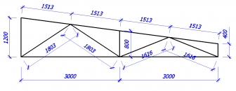
So, let's begin. Before calculating the farm, let's consider some real situation that you might encounter. For example, you need to cover a garage that is 6 meters wide and 9 meters long, but you have neither floor slabs nor beams. Only metal corners of various profiles. These are the ones we will use to assemble our farm!
Subsequently, purlins and corrugated sheeting will rest on the truss. The support of the truss on the walls of the garage is hinged.
First, you will need to know all the geometric dimensions and angles of your truss. This is where we need our mathematics, namely geometry. We find angles using the cosine theorem.

Then you need to collect all the loads on your farm (you can see it in the article). Suppose you have the following loading option:

Next, we need to number all the elements and nodes of the truss and set the support reactions (the elements are labeled in green, and the nodes in blue).
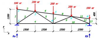
To find our reactions, we write the equilibrium equations for forces on the y-axis and the equilibrium equation for moments about node 2.
Ra+Rb-100-200-200-200-100=0;
200*1.5 +200*3+200*4.5+100*6-Rb*6=0;
From the second equation we find the support reaction Rb:
Rb=(200*1.5 +200*3+200*4.5+100*6) / 6;
Rb=400 kg
Knowing that Rb = 400 kg, from the 1st equation we find Ra:
Ra=100+200+200+200+100-Rb;
Ra=800-400=400 kg;
Once the support reactions are known, we must find the node where there are the fewest unknown quantities (each numbered element is an unknown quantity). From this point on, we begin to divide the truss into individual nodes and find the internal forces of the truss rods at each of these nodes. It is based on these internal efforts that we will select the sections of our rods.
If it turns out that the forces in the rod are directed from the center, then our rod tends to stretch (return to its original position), which means it itself is compressed. And if the forces of the rod are directed towards the center, then the rod tends to compress, that is, it is stretched.
So, let's move on to the calculation. In node 1 there are only 2 unknown quantities, so let’s consider this node (we set the directions of efforts S1 and S2 for our own reasons, in any case, we will get it right in the end).
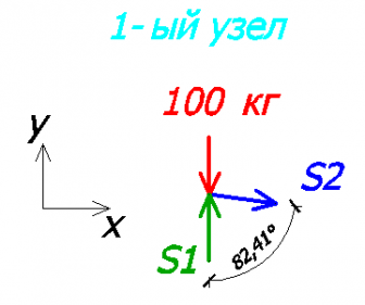
Consider the equilibrium equations on the x and y axes.
S2 * sin82.41 = 0; - on the x axis
-100 + S1 = 0; - on the y axis
From the 1st equation it is clear that S2=0, that is, the 2nd rod is not loaded!
From the 2nd equation it is clear that S1=100 kg.
Since the value of S1 turned out to be positive, it means that we chose the direction of effort correctly! If it turned out to be negative, then the direction should be changed and the sign changed to “+”.
Knowing the direction of force S1, we can imagine what the 1st rod is like.

Since one force was directed to the node (node 1), the second force will be directed to the node (node 2). This means our rod is trying to stretch, which means it is compressed.
Next, consider node 2. There were 3 unknown quantities in it, but since we have already found the value and direction of S1, only 2 unknown quantities remain.
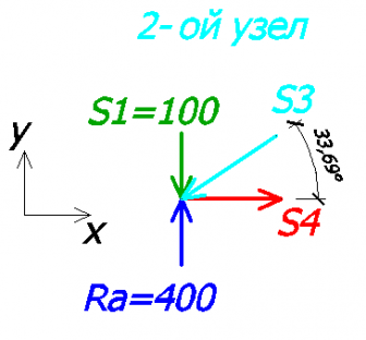
Yet again
100 + 400 – sin33.69 * S3 = 0 - on the y axis
- S3 * cos33.69 + S4 = 0 - on the x axis
From the 1st equation S3 = 540.83 kg (rod No. 3 is compressed).
From the 2nd equation S4 = 450 kg (rod #4 is stretched).
Consider the 8th node:
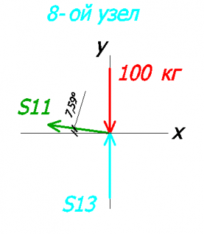
Let's create equations on the x and y axes:
100 + S13 = 0 - on the y axis
-S11 * cos7.59 = 0 - on the x axis
From here:
S13 = 100 kg (rod #13 compressed)
S11 = 0 (zero rod, no force in it)
Consider the 7th node:
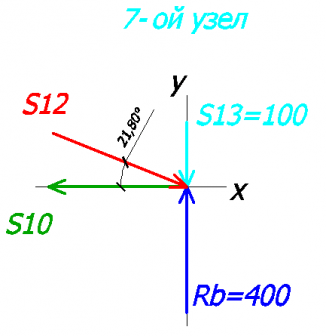
Let's create equations on the x and y axes:
100 + 400 – S12 * sin21.8 = 0 - on the y axis
S12 * cos21.8 - S10 = 0 - on the x axis
FROM the 1st equation we find S12:
S12 = 807.82 kg (rod #12 compressed)
From the 2nd equation we find S10:
S10 = 750.05 kg (rod #10 stretched)
Next, let's look at node No. 3. As far as we remember, the 2nd rod is zero, which means we won’t draw it.
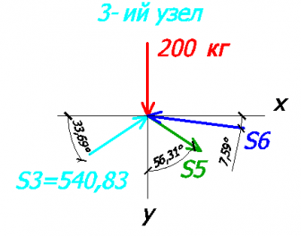
Equations on the x and y axis:
200 + 540.83 * sin33.69 – S5 * cos56.31 + S6 * sin7.59 = 0 - on the y axis
540.83 * cos33.69 – S6 * cos7.59 + S5 * sin56.31 = 0 - on the x axis
And here we will need algebra. I will not describe in detail the method for finding unknown quantities, but the gist is this: we express S5 from the 1st equation and substitute it into the 2nd equation.
As a result we get:
S5 = 360.56 kg (rod #5 stretched)
S6 = 756.64 kg (rod #6 compressed)
Let's consider node No. 6:
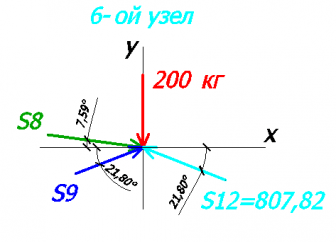
Let's create equations on the x and y axes:
200 – S8 * sin7.59 + S9 * sin21.8 + 807.82 * sin21.8 = 0 - on the y axis
S8 * cos7.59 + S9 * cos21.8 – 807.82 * cos21.8 = 0 - on the x axis
Just like in the 3rd node, we will find our unknowns.
S8 = 756.64 kg (rod #8 compressed)
S9 = 0 kg (rod No. 9 zero)
Let's consider node No. 5:

Let's make up the equations:
200 + S7 – 756.64 * sin7.59 + 756.64 * sin7.59 = 0 - per y axis
756.64 * cos7.59 – 756.64 * cos7.59 = 0 - on the x axis
From the 1st equation we find S7:
S7 = 200 kg (rod #7 compressed)
To check our calculations, let’s consider the 4th node (there are no forces in rod No. 9):

Let's create equations on the x and y axes:
200 + 360.56 * sin33.69 = 0 - per y axis
-360.56 * cos33.69 – 450 + 750.05 = 0 - on the x axis
In the 1st equation it turns out:
In the 2nd equation:
This error is acceptable and is most likely related to the angles (2 decimal places instead of 3).
As a result, we get the following values:

I decided to double-check all our calculations in the program and got exactly the same values:

Selection of cross-section of truss elements
At calculation of a metal truss after all the internal forces in the rods have been found, we can begin to select the cross-section of our rods.
For convenience, we summarize all values in a table.
Today, creating a shed is an affordable and truly practical solution. And it doesn’t matter at all what you are going to build - a dacha, a bathhouse, a private house or a garage, as such roof structure has a wide range of applications in residential construction. In addition, this type of roofing will require very modest financial costs for installation, as well as subsequent operation.
Advantages of lean-to structures
If you decide to build a pitched roof yourself, then you will not need any special professional skills or abilities. The main advantages of this type of roof are:
- simplicity of design (therefore, installation can be performed without the involvement of specialists);
- resistance to climatic influences, but only if you can choose the right angle of inclination of the slope;
- availability. The pitched roof has small room for the attic, so you can significantly save on heating your home;
- Efficiency of installation. Construction work will not take much time, so you can implement your roofing project in a really short time frame.

 Sheathing sections depending on the roof slope and rafter pitch
 All of the above advantages allow us to conclude that a pitched roof is a worthy and optimal choice. In addition, by giving preference to this design, you will be able to use the area of the second floor as a place to create an attic, even if load-bearing walls have different heights. As an addition, you can build a veranda or covered terrace, because the protruding edge of the slope does not fit tightly to the building.
Subtleties of creating a drawing
If you decide to give preference to a pitched roof, then first of all you will need to develop a project for the future roof. To do this, you will need to determine what the slope of the slope will be. Construction experts advise placing it in the windward direction. This will guarantee high degree reliability and safety of the flooring. Determine which direction the wind often blows at the construction site. Today, the only thing required to erect a structure is accurate calculations. This is necessary primarily in order to determine the maximum possible load on the supports, as well as to calculate the coefficient of atmospheric influence of precipitation. 

When designing a structure, leave a margin of endurance for the rafters in case the amount of snow falls sharply during the cold season.
As we have already said, creating a lean-to structure requires making the right choice tilt angle. But in this matter, you should not only take into account the terrain that is characterized by wind and snow, but also select the most suitable material for laying work. Shed roofing is a simple roof type that is used today in various buildings. This design requires minimal consumption of materials and time, since it has only one angle. Since this type of roof is often found in modern buildings, today you can see a huge number of projects of varying complexity on the Internet. 

IN construction work All kinds of building and insulating materials can be used. You yourself can determine what angle the roof of your house will have. But it is best not to give preference to large angles, since appearance the structure will not be very attractive. But in this case, you will not need to think about constantly cleaning the roofing from snow precipitation. To ensure that the roof is not only practical, but also functional, it is strongly recommended to use a special construction calculator for calculations.
Criteria and subtleties of calculations for the construction of a pitched roof
If you think that you will not be able to accurately carry out all the design calculations, then seek help from specialists. But in the case when the construction budget is limited, then for such work you can completely use a calculator of all design parameters. It will allow you to find out not only the angle of inclination, but also the surface area and optimal weight Supplies, as well as the number of rafters. Now let's look at all these characteristics in more detail.
Materials for insulation work
Helps determine how much insulation material will be needed for the roof covering. It is known that the length of the roll is 15 m and the width is 1 m. Calculation work is carried out taking into account an error of 10 percent for overlap. 

Rafter load level
The indicator will indicate the maximum permissible load on the rafter system of the structure. It will show how much weight the entire roofing structure has, as well as what impact it will have on the house, garage or cottage during the cold season due to snow deposits and strong winds.
Length and number of rafters
Shed roof slope angle calculation of the number of rafters that will be needed to install the roof, as well as the length of each element, depending on the location of the edges of the slope and the ridge of the structure.
Characteristics and cross-section of timber for rafters
To determine these indicators, experts in the construction industry strongly recommend using the table from the regulatory and technical documentation, namely from GOST 24454-80. It provides all the necessary information regarding wood materials that can be used when installing the roof, and also gives a range for calculating the cross-section of the rafters. For calculation work, you will need data on the coverage area, the selected material, as well as the exact loads that will be exerted on the roof during operation. 
Of course, these are not all the parameters that need to be determined before starting roofing work. In addition to those mentioned above, you need to determine the number of rows of sheathing and the maximum distance between the boards, find out the volume of each of them, etc. In any case, we strongly recommend that you do not undertake calculations if you do not have experience and even the slightest idea about the specifics of this matter. The main requirement is maximum accuracy. In order to be on the safe side, it is best to entrust the calculation pitched roof professionals.
Metal trusses made of profile pipe– metal structures, the assembly of which is carried out using lattice metal rods. Their production is a rather complex and time-consuming process, but the result usually lives up to expectations. An important advantage is the cost-effectiveness of the resulting design. During the production process, paired metal and gussets are often used as connecting metal parts. The further assembly process is based on riveting or welding.
Advantages of metal structures
A metal truss has many advantages. With their help, you can easily cover a span of any length. However, it should be understood that correct installation involves the initial competent calculation of a truss made of a profile pipe. In this case, you can be sure of the quality of the created metal structure. It is also worth adhering to the planned plans, drawings and markings so that the product turns out in accordance with the requirements.
The benefits of the product do not end there. The following advantages can be highlighted:
- Durability of a metal product.
- Low weight when compared with other similar designs.
- Endurance.
- Resistance to damage and negative environmental factors.
- Strong knots that contribute to resistance to any type of load.
- The opportunity to save money through self-assembly, since a finished metal product is not cheap.

- Contour of support belts. They will help determine the purpose of the metal structure, the angle of inclination and the type of roof.
- When selecting, it is necessary to follow the principle of economy, unless the requirements suggest the opposite.
- Dimensions are calculated taking into account the loads on the structure. It is important to remember that the angles of the rafters may vary, but the panel must match them.
- The last calculation concerns the spacing between nodes. Most often it is chosen to match the width of the panel.
Structural features of trusses
A profile pipe truss has characteristics, which should be remembered in advance. Based on the division, certain parameters can be distinguished. The main value is the number of belts. The following types can be distinguished:
Second important parameter, without which it is impossible to create a truss drawing, these are contours and shape. Depending on the latter, straight, gable or single-pitch, arched trusses can be distinguished. Along the contour, you can also divide metal structures into several options. The first is designs with a parallel belt. They are considered the optimal solution for creating soft roof. The metal support is extremely simple and its components are identical, the dimensions of the grid are the same as the rods, making installation an easy job.
The second option is single-pitched metal structures. They are based on rigid components that provide resistance to external loads. The creation of such a design is characterized by economical material and correspondingly low costs. The third type is polygonal farms. They are distinguished by time-consuming and rather complex installation, and the advantage is their ability to withstand heavy weight. The fourth option is triangular trusses made of profile pipes. They are used if you plan to create a metal truss with a large angle of inclination, but the disadvantage will be the presence of waste after construction. 
The next important parameter is the angle of inclination. Depending on it, metal trusses made of profile pipes are divided into three main groups. The first group includes metal structures with an inclination angle of 22-30 degrees. In this case, the length and height of the product are represented by a ratio of 1:5. Among the advantages of such a metal structure is its low weight. Most often, metal triangular trusses are created this way.
In this case, it may be necessary to use braces mounted from top to bottom if the span height exceeds 14 meters. In the upper chord there will be a panel 150-250 cm long. As a result, a structure with two belts and an even number of panels will be obtained. Provided that the span is more than 20 meters, a sub-rafter metal structure should be installed, connecting it with support columns.
The second group includes trusses made from square pipes or from corrugated pipes and other varieties, if the angle of inclination is 15-22 degrees. The ratio of height and length reaches 1:7. The maximum length of the frame should not exceed 20 meters. If it is necessary to increase the height, additional procedures are required, for example, a broken belt is created.
The third group includes metal structures with an inclination angle of less than 15 degrees. In these projects, a trapezoidal rafter system is used. They have additionally short stands. This makes it possible to increase resistance to longitudinal deflection. If a pitched roof is installed, the angle of inclination of which reaches 6-10 degrees, it is necessary to consider an asymmetrical shape. The division of the span can vary depending on the design features, and can reach seven, eight or nine parts.
Separately, there is a Polonceau farm, which is assembled with your own hands. It is represented by two triangular trusses, which are connected by a tie. This eliminates the installation of long braces that would have to be located in the middle panels. As a result, the weight of the structure will be optimal. 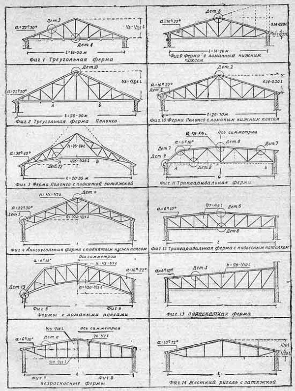
How to calculate the canopy correctly?
The calculation and manufacture of trusses from profile pipes should be based on the basic requirements specified in SNiP. When making calculations, it is important to draw up a drawing of the product, without which subsequent installation will be impossible. Initially, you should prepare a diagram that will indicate the main relationships between the roof slope and the length of the structure as a whole. In particular, the following should be taken into account:
It should be remembered that increasing the height with your own hands will lead to an increase in load-bearing capacity. In this case, the snow cover will not be retained on the roof. To further strengthen the metal structure, you will have to install stiffeners. To determine the dimensions of the farm, you should be guided by the following data:
- structures up to 4.5 meters wide are assembled from parts with dimensions of 40x20x2 mm;
- products with a width of 5.5 meters are created from components measuring 40x40x2 mm;
- if the width of the structure exceeds 5.5 meters, it is optimal to choose parts 40x40x3 mm or 60x30x2 mm.
Next, you need to calculate the pitch; for this, take into account the distance from one to the next canopy support. Often it is standard and reaches 1.7 meters. If you break this unspoken rule, the strength of the structure may be somewhat compromised. After all the required parameters have been calculated, it is necessary to obtain a design diagram. To do this, use a program to achieve the required strength. Most programs have a name similar to the process they execute. You can choose the program “Calculation of Truss”, “Calculation of Trusses 1.0” and other similar ones. 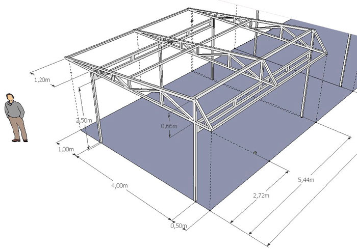
When calculating, be sure to take into account the cost of one ton of metal in the purchase, as well as the cost of manufacturing the metal structure itself, that is, the cost of welding, treatment with an anti-corrosion compound and installation. Now it remains to figure out how to weld a truss from a profile pipe.
In order for truss welding to be of high quality, it is necessary to follow a number of recommendations. Among them are the following:

In order for the design to turn out in accordance with the requirements, it is important to adhere to a certain operating algorithm. Initially, the site is marked. To do this, vertical supports and embedded parts are installed. If necessary, metal profile pipes can be immediately placed in the pits and concreted. The installation of vertical supports is checked with a plumb line, and to check parallelism, the cord is pulled.
-
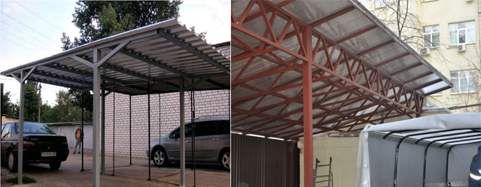
Sheds are classified as the simplest structures that are erected on a suburban or summer cottage. They are used for a variety of purposes: as a parking lot, storage area and many other options.
Structurally, the canopy is extremely simple. This
- frame, the main element of which is trusses for canopies, which are responsible for the stability and strength of the structure;
- coating. It is made of slate, polycarbonate, glass or corrugated sheet;
- additional elements. As a rule, these are decoration elements that are located inside the structure.
The design is quite simple, and it also weighs little, so you can assemble it with your own hands right on the site.
However, in order to get a practical, correct canopy, you first need to ensure its strength and long-term operation. To do this, you should know how to calculate a truss for a canopy, make it yourself and weld it or buy ready-made ones.
Metal trusses for canopies

This design consists of two belts. The upper and lower chords are connected through braces and vertical posts. It is able to withstand significant loads. One such product, weighing from 50–100 kg, can replace metal beams three times larger in weight. With proper calculation, the metal truss in, channels or does not deform or bend when exposed to loads.
A metal frame experiences several loads at the same time, which is why it is so important to know how to calculate a metal truss in order to accurately find the equilibrium points. This is the only way the structure can withstand even very high impacts.
How to choose material and cook them correctly

Creation and self installation canopies are possible with small dimensions of the structure. Trusses for canopies, depending on the configuration of the belts, can be made of profiles or steel angles. For relatively small structures It is recommended to choose profile pipes.
Such a solution has a number of advantages:
- Load bearing capacity profile pipe is directly related to its thickness. Most often, to assemble the frame, a material with a square cross-section of 30-50x30-50 mm is used, and for small structures, pipes of a smaller cross-section are suitable.
- For metal pipes They are characterized by greater strength and yet they weigh much less than a solid metal bar.
- Pipes are bent - a quality necessary when creating curved structures, for example, arched or domed.
- The price of trusses for sheds is relatively small, so buying them will not be difficult.
On a note
The metal frame will last much longer if it is protected from corrosion: treated with a primer and painted.
- On such metal carcass You can conveniently and quite simply lay almost any sheathing and roofing.
Methods for connecting profiles
How to weld a canopy
Among the main advantages of profile pipes, the non-shaped connection should be noted. Thanks to this technology, a truss for spans not exceeding 30 meters is structurally simple and relatively inexpensive. If its upper belt is sufficiently rigid, then the roofing material can be supported directly on it.
The formless welded joint has a number of advantages:
- The weight of the product is significantly reduced. For comparison, we note that riveted structures weigh 20%, and bolted structures weigh 25% more.
- Reduces labor and manufacturing costs.
- welding cost is low. Moreover, the process can be automated if you use devices that allow uninterrupted feeding of welded wire.
- the resulting seam and the attached parts are equally strong.
One of the disadvantages is the need to have experience in welding.
Bolt-on mounting
Bolted connections of profile pipes are not used very rarely. It is mainly used for collapsible structures.
The main advantages of this type of connection include:
- Simple assembly;
- No need for additional equipment;
- Possible dismantling.
But at the same time:
- The weight of the product increases.
- Additional fasteners will be required.
- Bolted connections are less strong and reliable than welded ones.

How to calculate a metal truss for a canopy made from a profile pipe

The structures being erected must be rigid and strong enough to withstand various loads, therefore, before installing them, it is necessary to calculate a truss from a profile pipe for a canopy and draw up a drawing.
When calculating, as a rule, they resort to the help of specialized programs taking into account the requirements of SNiP (“Loads, impacts”, “Steel structures”). You can calculate a metal truss online using the metal profile canopy calculator. If you have the appropriate engineering knowledge, you can carry out the calculation yourself.
On a note
If the main design parameters are known, you can look for a suitable finished project, among those posted on the Internet.

Design work is carried out on the basis of the following initial:
- Drawing. The configuration of the frame belts depends on the type of roof: single or gable, hip or arched. The most simple solution can be considered a single-pitched truss made from a profile pipe.
- Design dimensions. The larger the trusses are installed, the greater the load they can withstand. The angle of inclination is also important: the greater it is, the easier it will be to remove snow from the roof. For the calculation, you will need data on the extreme points of the slope and their distance from each other.
- Dimensions of roofing material elements. They are playing decisive role in determining the pitch of trusses for a canopy, say, . By the way, this is the most popular coating for structures built on their own plots. They bend easily, so they are suitable for constructing curved coverings, for example, arched ones. All that matters is how to do it right calculate a polycarbonate canopy.
The calculation of a metal truss from a profile pipe for a canopy is performed in a certain sequence:
- determine the span corresponding to the technical specifications;
- to calculate the height of the structure, substitute the span dimensions according to the presented drawing;
- set the slope. According to the optimal shape of the roof of the structure, the contours of the belts are determined.
On a note
The maximum possible pitch of trusses for a canopy when using a profile pipe is 175 cm.
How to make a polycarbonate truss

The first stage of making your own trusses from a profile pipe for a canopy is to draw up a detailed plan, which should indicate the exact dimensions of each element. In addition, it is advisable to prepare an additional drawing of structurally complex parts.
As you can see, before you make trusses yourself, you need to be well prepared. Let us note once again that while the choice of product shape is guided by aesthetic considerations, a calculation path is required to determine the structural type and number of constituent elements. When checking the strength of a metal structure, it is also necessary to take into account data on atmospheric loads in a given region.
The arc is considered an extremely simplified variation of the truss. This is one profiled pipe with a round or square cross-section.
Obviously, this is not only the simplest solution, it is also cheaper. However, polycarbonate canopy poles have certain disadvantages. In particular, this concerns their reliability.

arched canopies photos
Let's analyze how the load is distributed in each of these options. The design of the truss ensures uniform distribution of the load, that is, the force acting on the supports will be directed, one might say, strictly downward. This means that the support pillars perfectly resist compression forces, that is, they can withstand the additional pressure of the snow cover.
The arches do not have such rigidity and are not able to distribute the load. To compensate for this kind of impact, they begin to unbend. The result is a force placed on the supports at the top. If we take into account that it is applied to the center and directed horizontally, then the slightest error in calculating the base of the pillars will, at the very least, cause their irreversible deformation.
An example of calculating a metal truss from a profile pipe
The calculation of such a product assumes:
- determination of the exact height (H) and length (L) of the metal structure. The latter value must exactly correspond to the span length, that is, the distance overlapping the structure. As for the height, it depends on the designed angle and contour features.
In triangular metal structures, the height is 1/5 or ¼ of the length, for other types with straight belts, for example, parallel or polygonal - 1/8.
- The angle of the grid braces ranges from 35–50°. On average it is 45°.
- It is important to determine the optimal distance from one node to another. Usually the required gap coincides with the width of the panel. For structures with a span length of more than 30 m, it is necessary to additionally calculate the construction lift. In the process of solving the problem, you can obtain the exact load on the metal structure and select the correct parameters for the profile pipes.

As an example, consider the calculation of trusses for a standard 4x6 m lean-to structure.
The design uses a 3 by 3 cm profile, the walls of which are 1.2 mm thick.
The lower belt of the product has a length of 3.1 m, and the upper one – 3.90 m. Between them, vertical posts made of the same profile pipe are installed. The largest of them has a height of 0.60 m. The rest are cut out in descending order. You can limit yourself to three racks, placing them from the beginning of the high slope.

The areas that are formed in this case are strengthened by installing diagonal lintels. The latter are made of a thinner profile. For example, a pipe with a cross section of 20 by 20 mm is suitable for these purposes. At the point where the belts meet, stands are not needed. On one product you can limit yourself to seven braces.
Five similar structures are used per 6 m length of the canopy. They are laid in increments of 1.5 m, connected by additional transverse jumpers made from a profile with a section of 20 by 20 mm. They are fixed to the upper chord, arranged in increments of 0.5 m. The polycarbonate panels are attached directly to these jumpers.
Calculation of an arched truss

The manufacture of arched trusses also requires precise calculations. This is due to the fact that the load placed on them will be distributed evenly only if the created arc-shaped elements have ideal geometry, that is, the correct shape.
Let's take a closer look at how to create an arched frame for a canopy with a span of 6 m (L). We will take the distance between the arches to be 1.05 m. With a product height of 1.5 meters, the architectural structure will look aesthetically pleasing and will be able to withstand high loads.
When calculating the profile length (mн) in the lower belt, use the following formula for the sector length: π R α:180, where the parameter values for this example in accordance with the drawing are equal, respectively: R= 410 cm, α÷160°.

After substitution we have:
3.14 410 160:180 = 758 (cm).
The structural units should be located on the lower chord at a distance of 0.55 m (rounded) from each other. The position of the extremes is calculated individually.
In cases where the span length is less than 6 m, welding of complex metal structures is often replaced with a single or double beam, bending metallic profile under a given radius. Although there is no need to calculate the arched frame, however correct selection profiled pipe still remains relevant. After all, the strength of the finished structure depends on its cross-section.
Calculation of an arched truss from a profile pipe online
How to calculate the arc length for a polycarbonate canopy
The arc length of an arch can be determined using Huygens' formula. The middle is marked on the arc, designated by point M, which is located on the perpendicular CM drawn to the chord AB, through its middle C. Then you need to measure the chords AB and AM.The arc length is determined by the Huygens formula: p = 2l x 1/3 x (2l – L), where l is the chord AM, L is the chord AB)
The relative error of the formula is 0.5% if the arc AB contains 60 degrees, and as the angular measure decreases, the error drops significantly. For an arc of 45 degrees. it is only 0.02%.