Estimate for strip foundation calculator. How to calculate the foundation for a private house? Calculation of the support area, dimensions of the base, reinforcement and concrete
The construction of any building is preceded by design work, during which the type of foundation base and the required amount of materials for its construction are determined. An important part of the foundation is the reinforcing cage. It increases the strength of the base, dampens tensile and bending loads, and prevents cracking. To perform the work, it is necessary to understand how much reinforcement is needed to reinforce the strip foundation, as well as for the columnar and slab base. Let's deal with the features of calculations.
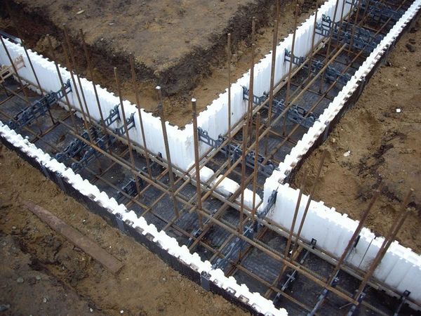
Consumption of reinforcement for reinforcing a strip foundation
Getting ready to calculate the amount of reinforcement for the foundation - important points
When planning the construction of a private house, you should pay attention Special attention on the design of the reinforcing lattice, which perceives significant loads on the foundation. A well-designed scheme of the load-bearing grid and the use of the optimal cross-section of the reinforcement makes it possible to provide the required margin of safety of the foundation base, as well as its long service life.
- using software tools and online calculators that perform the calculation of reinforcement after the introduction of operating parameters;
- performing manual calculations based on information about design features foundation, the magnitude of the forces and the lattice parameters.
The foundation base, perceives the load from the mass of the building and evenly distributes it on the supporting surface of the soil.
The construction of buildings is carried out on various types of foundations:
- tape;
- plate;
- columnar.
 Calculation of reinforcement for a strip foundation
 Before starting calculations, you should deal with the design of the power frame, which consists of the following elements:
- vertical and cross rods, between which an equal interval is maintained;
- knitting wire connecting longitudinally located jumpers and vertical bars;
- couplings providing a strong connection and lengthening of reinforcing bars.
For each type of foundation, its own foundation reinforcement scheme is applied, which depends on the following factors:
- soil characteristics;
- building dimensions;
- structural features of the building;
- active loads.
Reinforcement is used, which has a ribbed surface, which differs:
- section size;
- class;
- the level of perceived loads;
- location in the power grid;
- cost.
 Laying reinforcement in strip foundation
 For various foundations, based on calculations, the following information is determined:
- the amount of reinforcement for the foundation;
- range of vertical and transverse bars;
- total mass of the reinforcing cage;
- methods of fixing steel rods in a load-bearing structure;
- carrier grid assembly technology;
- step of tying reinforcing elements.
It is important to correctly calculate. The reinforcement for the foundation in this case will provide the necessary margin of safety. Consider what initial data are needed for calculations, and also study the methodology for performing calculations for various types of foundations.
Calculation of the amount of reinforcement for a strip foundation
The base of the tape type provides increased stability of buildings on various soils. The design is a concrete strip that follows the contour of the building and is located under the main walls. Strengthening with steel reinforcement increases the strength characteristics of the concrete base and has a positive effect on its durability. For the construction of a spatial lattice, reinforcement with a diameter of 10 mm can be used.
Initial data for performing calculations:
- length and width of the foundation base;
- section of reinforced concrete tape;
- spacing between frame elements;
- the total number of strapping belts;
- power grid cell size.
 How much reinforcement is needed for the foundation
 Consider the order of calculations:
- Calculate the total length of the tape loop.
- Calculate the number of elements in the belts.
- Determine the footage of the horizontal rods.
- Calculate the need for vertical bars.
- Calculate the length of the cross bars.
- Add up the resulting footage.
Knowing the total number of butt sections, you can calculate the need for knitting wire.
Calculation of the amount of reinforcement for a slab-type foundation
The foundation of a slab structure is used for the construction of residential buildings on heaving soils. To ensure strength characteristics, reinforcing bars with a diameter of 10–12 mm are used. With an increased mass of buildings, the diameter of the bars should be increased to 1.4–1.6 cm.
- a spatial frame of reinforcement is constructed in two levels;
- the connection of the rods is made in the form of square cells with a side of 15–20 cm;
- binding is done with annealed wire at each connection point.
 Scheme of reinforcement of a monolithic foundation slab
 To determine the need for reinforcement, perform the following operations:
- Determine the number of horizontal bars in each tier.
- Calculate the total footage of the reinforcing bars that form the cells.
- Add the total length of the vertical supports connecting the tiers.
Adding the obtained values, we get the total need for reinforcement. Knowing the number of joints, it is easy to determine the required volume of steel wire.
How to calculate reinforcement for the foundation of a columnar structure
The base of the columnar type is widely used for the construction of various buildings. It consists of reinforced concrete supports of square and round section installed in the corners of the building, as well as at the intersection points of the main walls and internal partitions. To increase the strength of the supporting elements, ribbed rods with a cross section of 1–1.2 cm are used.
- the frame of the square profile support element is formed from 4 rods;
- the lattice of a reinforced concrete support of a circular cross section is made of three rods;
- the length of the reinforcement elements corresponds to the dimensions of the support column;
- transverse piping of the frame of the support column is made in increments of 0.4–0.5 m.
 Algorithm for calculating the consumption of foundation reinforcement
 - Determine the length of the vertical bars in one support.
- Calculate the footage of the elements of the transverse strapping of one frame.
- Calculate the total length by adding the values obtained.
Multiplying the result by the number of supports, we get the total length of the reinforcement.
How to calculate reinforcement for a foundation - an example of calculations
As an example, consider how much reinforcement is needed for a 10x10 foundation, formed in the form of a monolithic reinforced concrete tape.
To perform calculations, we use the following information:
- base width 60 cm, allows you to lay 3 horizontal rods in each belt;
- 2 reinforcement belts are performed, connected by vertical bars with an interval of 1 m.
- for a building 10x10 m and a foundation depth of 0.8 m, reinforcement with a diameter of 10 mm is used.
 Consumption of reinforcement for strip foundation
 - We determine the perimeter of the foundation of the building by adding up the length of the walls - (10 + 10) x2 = 40 m.
- We calculate the number of horizontal elements in one belt by multiplying the perimeter by the number of rods in one tier - 40x3 = 120 m.
- The total length of the longitudinal bars is determined by multiplying the obtained value by the number of tiers 120x2 = 240 m.
- We calculate the number of vertical elements installed in 10 pairs on each side 10x2x4 = 80 pcs.
- The total length of the vertical rods will be 80x0.8=64 m.
- We determine the length of jumpers with a size of 0.6 m each, installed on two belts (20 per side) - 10x2x4x0.6 = 48 m.
- Adding the length of the reinforcing bars, we get a total footage of 240 + 64 + 48 = 352 m.
Determining the length of steel wire is easy. The number of connections multiplied by the length of one piece of wire, equal to 20-30 cm, will give the desired result.
Summing up - how necessary is the calculation of reinforcement for the foundation
When planning the construction of a house, a bathhouse or a summer cottage, it is easy to determine the need for fittings with your own hands. Step by step instructions will allow using the calculator to calculate the footage of the rods for the manufacture of a reinforcing mesh that reinforces the foundation of the building. Knowing how to calculate reinforcement, you can independently perform calculations without resorting to the help of third-party specialists. Correctly performed calculations will ensure the strength of the foundation, the stability of the building, as well as a long service life.
IN cottage construction the most commonly used tape base, which, by right, is considered universal. You can build it without involving specialists with your own hands. The main thing is to perform all the calculations correctly, including the required amount of reinforcement for the construction of a strip foundation.
The tape base is a monolithic closed reinforced concrete strip passing under each load-bearing wall of the building. Such a foundation is most often used in individual construction, since has good set required characteristics and excellent value for money.
It distributes the load along the entire perimeter and prevents subsidence and deformation of the building due to the existing forces of soil buckling. Wherein . Some amateurs do not consider it necessary to reinforce the foundation. But this process is very important.
Indeed, in the end, the tape base acquires the following properties:
- strength, reliability and durability;
- ease of installation;
- the possibility of waterproofing reinforced rods.
Reinforcing steel frame is the power skeleton of a concrete foundation
Therefore, to increase the service life of the entire building, reinforcement is indispensable. But the main thing is not only to correctly strengthen the foundation, but also to calculate it correctly.
The planning of the foundation must be done especially scrupulously, because. in case of deformation, it can affect the entire building, and fixing it can be very difficult and costly. Calculation of the amount of materials required for the strip foundation and rolled steel you can do it yourself, or you can use the service online calculator.
An example of calculating a strip foundation
To perform the calculation of the strip foundation, it is necessary:
- calculate how much the house weighs without taking into account the foundation;
- determine snow and wind loads;
- choose the type of base.
- calculate the area of the sole of the foundation, given bearing capacity soil.
Snow load can be calculated based on SNiP 2.01.07-85. Section 5 contains data for all districts. It is quite difficult to calculate the wind load of a strip foundation. You can use the simplified formula: (15 x h + 40) x S, where h is the height from the ground to the top of the building, and S is the area of the structure.
 When calculating the weight of a building, it is necessary to take into account the approximate weight of furniture and equipment in the room. For example, with a building mass of 13384 kg, payload 11340 kg, snow - 8820 kg, and wind - 4410 kg, the calculations will look like this. Summing up these data, we get the figure 37954 kg. To it must be added 30% for errors. As a result, the total load on the base is 49340 kg.
In order to calculate the strip foundation, it is necessary to take into account its length of the base and the area of \u200b\u200bthe sole. So if the length bearing wall-30 m (3000 cm), then: 24670/3000=8.2 cm. This figure is the minimum width of the tape base. But it must be taken into account that the thickness of the walls must be greater than the width of the foundation.
In order to calculate how much concrete is needed, it is necessary to multiply the length of the bearing wall by the amount by which the foundation must be laid and by the width of the foundation. So, if the foundation on sandy soil is laid to a depth of 0.5 m, the width of the base is 20 cm (0.2 m), the length of the bearing wall is 30 m, then the calculation will look like this: 30 x 0.5 x 0.2 = 3 m3.
All materials for the foundation must be purchased with a small margin of 10-15%
Reinforcement calculation
Next, you need to calculate how much material is needed for reinforcing work. For example, the diameter of a steel bar will be 12 mm, according to the plan in the casting - 2 horizontal rods, and vertically, for example, the rods will be located in 0.5 m increments. The perimeter is 27 meters. So, 27 must be multiplied by 2 (horizontal rods), it turns out 54 m.
Similarly, we count vertical rods: 54/2 + 2 = 110 rods (108 intervals of 0.5 m and two on the sides). To account for the bars at the corners, you need to add 1 more rod, it turns out 114. If we take the height of the rod -70 cm, we calculate the length of the material: 114 x 0.7 = 79.8 m.
The easiest way to calculate reinforcement for a strip foundation is to use an online service - a calculator.
Formwork calculation
If the parameters of the boards are: the thickness is 2.5 cm, the length is 6 m and the width is 20 cm, then the calculation will be as follows. The formula calculates the area of the side surfaces: the perimeter is multiplied by the height of the casting, and then by 2 more (the fact that the inner perimeter is less than the outer one is not taken into account): (27 x 0.2) x 2 = 10.8 m2. Board area: 6 x 0.2 = 1.2 m2, 10.8 / 1.2 = 9.

So the result is 9 wooden planks, which will be 6 meters long. To this number is added a small number of boards for connections(at the discretion of the builder). As a result: 134 m of reinforcing materials and 27 linear meters of wooden bars 20 cm wide will be needed. The number of fasteners was not taken into account in the example. The received data are rounded off.
The calculation of reinforcement for a floor slab can also be performed using an online calculator.
Reinforcement scheme
More longitudinal tensions appear on the strip foundation than transverse ones. Therefore, rods with a smooth surface can be chosen as transverse rods, and corrugated rods as longitudinal rods. Most of the load on the corners. Therefore, when reinforcing them, it is necessary that one end of the rod goes into one wall, and the other into another.
The reinforcement process should begin with the installation of formwork. Inside it must be laid out with a layer of parchment. The main purpose of the formwork is to facilitate the removal of the structure. The task of the frame is to evenly distribute all loads on the base.
His scheme is simple:
- steel rods are driven into the bottom of the trench, equal in length to the depth of the foundation. It is necessary that the formwork should be, on average, 50 mm in increments of 400-600 mm;
- install stands (80-100 mm);
- 2-3 threads of the lower row of rods are attached to them. For stands, you can use bricks by placing them on the ribs;
- at the top and bottom, the rows are fixed with transverse jumpers to the vertical pin;
- the places where they intersect are fastened with a viscous wire or welding.
When calculating and erecting a strip foundation, it is recommended to take into account the requirements of SNiP so that the structure is strong and durable
Welding contributes to overheating of the metal and entails a change in properties. The thickness of the rods in such places also decreases. That's why wire is more often used for knitting. After reinforcement, it is only necessary to make holes for ventilation and fill the trenches with concrete mortar.
Reinforcement cost
Reinforcement can be bought at hardware stores. Its quantity is calculated in running meters. Therefore, in order to find out how many meters are required and calculate the final price, needed rolled weight table. Next, we calculate according to the formula: (number of metal rods in running meters) and multiply by (weight of 1 running meters of rods for the corresponding diameter) multiply by (cost of 1 ton of rods) / 1000.
The weight of the reinforcement depending on the section can be found in the table:
| Rebar diameter | Kilogram in 1 meter | meters to kilograms | meters in 1 ton |
| Armature 5 | 0,187 | 5,347 | 5347 |
| Armature 6 | 0,222 | 4,5045 | 4504 |
| Armature 8 | 0,395 | 2,53165 | 2531 |
| Armature 10 | 0,617 | 1,62075 | 1620 |
| Armature 12 | 0,888 | 1,12613 | 1126 |
| Armature 14 | 1,21 | 0,82645 | 826 |
| Armature 16 | 1,58 | 0,63291 | 633 |
| Armature 18 | 2 | 0,5 | 500 |
| Armature 20 | 2,47 | 0,40486 | 405 |
| Armature 22 | 2,98 | 0,33557 | 335 |
| Armature 24 | 3,85 | 0,25974 | 260 |
| Fittings25 | 4,83 | 0,20704 | 207 |
| Armature 28 | 6,31 | 0,15848 | 158 |

Reinforcement with a diameter of 12 mm and a corrugated or smooth surface is in great demand. It can be sold in bars and coils.
The approximate price with a diameter of 12 mm per 1 m can be found in the table:
| Name | Price per meter, rub |
| A1 12 mm | 21,78 |
| A3 A400 12 mm | 21,05 |
| A3 A500C 12 mm | 21,05 |
| A3 25G2S 12 mm | 22,98 |
| 35GS 12 mm | 22,7 |
Reinforcing a strip base is not at all difficult, although this is a rather energy-intensive and financially investing process. But saving doesn't make sense. By choosing the right reinforcement and calculating its quantity, you can strengthen the foundation, while extending the life of the entire building.
An example of self-calculation of a strip foundation can be viewed in the video:
Then the cross-sectional area will be:
40 100 = 4000 cm2.
We define total area reinforcement section (minimum):
4000: 1000 = 4 cm2.
Since the width of the tape is 40 cm, 2 rods must be placed in one lattice, and the total number is 4 pcs.
Then the minimum cross-sectional area of one bar will be 1 cm2. According to the tables of SNiP (or from other sources), we find the closest value. In this case, reinforcing bars 12 mm thick can be used.
Determine the number of longitudinal rods. Let's say the total length of the tape is 30 m (tape 6: 6 m with one jumper 6 m).
Then the number of working rods with a length of 6 m will be:
(30:6) 4 = 20 pcs.
Determine the number of vertical bars. Let's say the step of the clamps is 50 cm.
Then, with a tape length of 30 m, you will need:
30: 0.5 = 60 pcs.
Determine the length of one clamp.
To do this, subtract 10 cm from the width and height of the section and add up the results:
(40 - 10) + (100 - 10) \u003d 120 cm. The length of one collar is 120 2 \u003d 140 cm \u003d 2.4 m.
Total length of vertical reinforcement:
2.4 60 \u003d 144 m. The number of rods with a length of 6 m will be 144: 6 \u003d 24 pcs.
NOTE!
The values obtained should be increased by 10-15% in order to have a margin in case of errors or unforeseen material costs.

Types and sizes
There are two main :
- Metal.
- Composite.
The metal rods used to assemble the reinforcing cage have a ribbed or smooth surface.
Ribbed rods go to horizontal (working) reinforcement, as they have an increased adhesive force with concrete, which is necessary for the high-quality performance of their functions.
Vertical bars, as a rule, are smooth, since their task is to maintain the working rods in the desired position until the moment of pouring. The diameter of the rods ranges from 5.5 to 80 mm. working rods of 10, 12 and 14 mm and smooth 6-8 mm are used.
Composite reinforcement consists of different elements:
- Glass.
- Carbon.
- Basalt.
- Aramid.
- polymer additives.
Most widely used fiberglass reinforcement.
It has the greatest strength, the most rigid and resistant to tensile loads of all other options.
Like all types of composite rods, fiberglass reinforcement is completely resistant to moisture.
Manufacturers claim that performance is unchanged throughout the entire service life, but in practice the validity of such a statement has not yet been verified. The problem of composite reinforcement is the complexity of the technology, due to which the quality of the material differs markedly from different manufacturers.
In addition, composite rods are not able to bend, which is inconvenient when assembling frames and reduces strength. corner connections frame.
IMPORTANT!
Among builders, the attitude towards composite reinforcement is complex. Without denying positive qualities, they do not trust the little-studied building materials, not passed full cycle operation. In addition, metal reinforcement has well-defined specifications, while composite species have a rather large spread of properties. All these factors limit the use of composite rods.

How to make the right choice
The choice of reinforcing bars is based on design data and the preferences of the builders.
Metal rods are usually chosen, although composite reinforcement is increasingly used in construction every year. strip bases. Preference is given to metal rods because of the ability to give them the necessary bend, which is impossible to do with fiberglass rods.
This is especially important in the construction of belts with curved sections or in the presence of fracture angles other than 90°.
In addition, metal reinforcement is more economical, as it allows you to make clamps from one bar, without having to create multiple connection points.
The diameters of the rods have long been worked out in practice, they are often chosen without preliminary calculation - at about 30 cm a 10 mm rod is used, for tapes 40 cm wide, 12 mm rods are chosen, and with a width of more than 50 cm - 14 mm. The thickness of the vertical reinforcement is determined by the height of the tape, up to 70 cm choose 6 mm, and at a height of over 70 cm - 8 mm or more.

Useful video
In this section, you can also see how the calculation is performed using the example of a real construction site:
Conclusion
A well-chosen reinforcement scheme and the material itself ensure the strength and resistance of the tape to possible loads.
Difficult and problematic soils, prone to heaving or seasonal movements, require a responsible and careful approach to.
It must be taken into account that all design values determine the minimum design parameters that require some increase for a certain margin of safety.
When choosing reinforcement and a reinforcement scheme, it is necessary to multiply all values by 1.2-1.3 (reliability factor) in order to reduce the risk of unforeseen factors.
In contact with
A shallow-depth strip foundation (hereinafter referred to as MZLF) is one of the types of strip foundations, which is characterized by a slight deepening, much less than the depth of soil freezing, and a relatively small consumption of concrete mix. This article discusses the main advantages and disadvantages of MZLF, the most common mistakes during their construction, a simplified calculation method suitable for private developers (non-professionals), recommendations for building a foundation with your own hands.
The main advantages of MZLF are:
- efficiency - the consumption of concrete is much lower than in the construction of a conventional strip foundation. It is this factor that most often determines the choice of this technology in low-rise construction;
- reduced labor costs - less earthwork, less volume of prepared concrete (this is especially important when it is not possible to pour the finished mixture from the mixer);
- smaller tangential frost heaving forces due to the reduced area of the lateral surface of the foundation.
However, during the construction of the MZLF, it is necessary to strictly observe the technology, a frivolous attitude to the process can lead to cracks, and then all of the above advantages, as they say, will go down the drain.
The most common mistakes made with the MZLF device:
1) the choice of the main working dimensions of the foundation without any (even the most simplified) calculation at all;
2) pouring the foundation directly into the ground without sprinkling with non-porous material (sand). According to fig. 1 (on the right) it can be said that in the winter season the soil will freeze to concrete and, rising, drag the tape up, i.e. the tangential forces of frost heaving will act on the foundation. This is especially dangerous if the MZLF is not insulated and a high-quality blind area is not equipped;
3) incorrect reinforcement of the foundation - the choice of the diameter of the reinforcement and the number of rods at your discretion;
4) Leaving the MZLF unloaded for the winter - it is recommended that the entire cycle of work (construction of the foundation, erection of walls, and arrangement of the blind area) be performed one construction season before the onset of severe frosts.
Calculation of a shallow strip foundation.
The calculation of the MZLF, like any other foundation, is based, firstly, on the value of the load from the weight of the house itself and, secondly, on the calculated soil resistance. Those. The ground must support the weight of the house, which is transferred to it through the foundation. Please note that it is the ground that holds the mass of the house on itself, and not the foundation, as some believe.
If, if desired, an ordinary private developer can still calculate the weight of the house (for example, using our online calculator located), then it is not possible to determine the calculated soil resistance on your site on your own. This characteristic calculated by specialized organizations in specialized laboratories after geological and geodetic surveys. Everyone knows that this procedure is not free. Basically, architects who make a project at home resort to it, and then they calculate the foundation based on the data received.
In this regard, it makes no sense to give formulas for calculating the size of the MZLF within the framework of this article. We will consider the case when the developer is building on his own, when he does not conduct geological and geodetic surveys and cannot accurately know the calculated soil resistance on his site. In such a situation, the dimensions and design of the MZLF can be selected from the tables below.
The characteristics of the foundation are determined depending on the material of the walls and ceilings of the house and its number of storeys, as well as on the degree of heaving of the soil. How can you determine the latter is described
I. MZLF on medium and strongly heaving soils.
Table 1: Heated buildings with walls made of lightweight brickwork or aerated concrete (foam concrete) and with reinforced concrete floors.

Notes:
- the number in brackets indicates the material of the pillow: 1 - sand of medium size, 2 - coarse sand, 3 - a mixture of sand (40%) with crushed stone (60%);
- this table can also be used for houses with wooden floors, the margin of safety will be even greater;
- options for foundation designs and reinforcement options, see below.
Table 2: Heated buildings with insulated timber panel walls ( frame houses), logs and timber with hardwood floors.

Notes:
- the numbers in brackets indicate the same as in table 1;
- above the value line for walls made of insulated wooden panels, below the line - for log and timber walls.
Table 3: Unburied foundations of unheated log and timber structures with wooden floors.

Notes:
- above the value line for log walls, below the line - for walls made of timber.
Design options for MZLF on medium and highly heaving soils, indicated in the tables with letters, are shown in the figures below:

1 - monolithic reinforced concrete foundation; 2 - sand filling of the sinuses; 3 - sand (sand-gravel) pillow; 4 - reinforcing cage; 5 - blind area; 6 7 - waterproofing; 8 - plinth; 9 - ground surface; 10 - sand bedding; 11 - turf.
Option a.- the upper plane of the foundation coincides with the surface of the earth, the plinth is made of bricks.
Option b.- the foundation protrudes 20-30 cm above the surface, forming a low base or being part of the base.
Option c.- the foundation rises above the ground by 50-70 cm, while it is also the base.
Option g.- non-buried foundation-basement; Table 3 shows that such foundations are used for unheated wooden buildings.
Option d.- used instead of options b. or V. when the width of the sole of the foundation significantly exceeds the thickness of the wall (by more than 15-20 cm).
Option e.- a shallow-depth strip foundation on sandy bedding is used quite rarely on weak (peaty, silty) soils with high level ground water for wooden buildings. Depending on the size of the building, backfilling is done either under each tape, or under the entire foundation at once.
Reinforcement of a shallow strip foundation.
Reinforcement of MZLF is made with meshes of working reinforcement and auxiliary reinforcing wire. The working reinforcement is located in the lower and upper parts of the foundation, while it must be immersed in the concrete thickness by about 5 cm. It makes no sense to place working reinforcement in the middle of the tape (as you can sometimes see on the Internet).
Table 4: Foundation reinforcement options.

The MZFL reinforcement schemes are shown in the following figure:

A.- mesh with two bars of working reinforcement; b.- mesh with three bars of working reinforcement; V.- T-shaped joint; G.- L-shaped corner joint; d.- additional reinforcement of the MZLF with a large width of the sole, when the sole is wider than the base by more than 60 cm (additional mesh is located only in the lower part.
1 - working fittings (A-III); 2 - auxiliary reinforcing wire ∅ 4-5 mm (Вр-I); 3 - rods of vertical reinforcement ∅ 10 mm (A-III), connecting the upper and lower grids; 4 - reinforcement for reinforcing the corner ∅ 10 mm (A-III); 5 - connection with wire twists (the length of the twist is at least 30 diameters of the working reinforcement); 6 - additional working reinforcement ∅ 10 mm (A-III).
II. MZLF on non-rocky and weakly rocky soils.
Shallow-buried strip foundations on non-rocky and slightly heaving soils do not have to be made only from monolithic concrete. You can use other local materials, such as rubble stone, red ceramic bricks. MZLF is laid at 0.3-0.4 meters without a sand cushion. Moreover, for wooden buildings and one-story brick (or aerated concrete) foundations, you can not even reinforce them.
For 2 and 3 storey houses with walls made of stone materials, the MZLF is reinforced. Concrete foundations are reinforced according to the 1st reinforcement option (see table 4 above). Foundations made of rubble or brick are reinforced with masonry meshes made of Vp-I reinforcement ∅ 4-5 mm with a mesh size of 100x100 mm. Nets are laid every 15-20 cm.
The structures of the MZLF on non-rocky and slightly heaving soils are shown in the figure below:

1 - foundation; 2 - plinth; 3 - blind area; 4 - waterproofing; 5 - draft floor (shown conditionally); 6 - mesh of wire reinforcement, 7 - reinforcement according to the 1st option (see tab. 4)
Options a. and b.- for wooden and one-story brick (aerated concrete) buildings.
Options in. and Mr.- for two- and three-story brick (aerated concrete) buildings.
The width of the sole b is determined depending on the number of storeys of the building and the material of the walls and ceilings.
Table 5: The values of the width of the sole of the MZLF on non-rocky and low-rocky soils.

Stages of construction of a shallow strip foundation and recommendations.
1) Before proceeding with the construction of the foundation, if necessary, it is necessary to ensure high-quality drainage of surface rainwater from neighboring areas from the building site. This is done by cutting drainage ditches.
2) The foundation is marked and trenches come off. It is recommended to start earthworks only after delivery to the construction site of all necessary materials. The process of extracting the trench, pouring the tape, backfilling the sinuses and constructing the blind area is desirable to organize continuous. The less time it takes, the better.
3) Dug trenches are covered with geotextiles. This is done so that the sand cushion and the sandy backfill of the sinuses do not eventually become silted up with the soil surrounding them. At the same time, geotextiles freely pass water and do not allow plant roots to germinate.
4) In layers (layers of 10-15 cm), a sand (sand-gravel) pillow is poured with careful tamping. Use either manual rammers, or areal vibrators. Do not take ramming lightly. Shallow foundations are not as strong as foundations filled to the full depth of freezing, and therefore a freebie here is fraught with the appearance of cracks.
5) The formwork is exposed and the reinforcing cage is knitted. Do not forget to immediately provide for the supply of water and sewer to the house. If the foundation is also a plinth, remember about the ventilation (does not apply to buildings with floors on the ground).
6) Concrete is being poured. The filling of the entire tape must be carried out continuously, as they say, in one go.
7) After the concrete has set (3-5 days in summer), the formwork is removed and vertical is made.
8) The sinuses are backfilled with coarse sand with layer-by-layer tamping.
9) A blind area is being built. It is advisable (especially with a low height of the foundation tape) to make the blind area insulated. This measure will further reduce the frost heaving forces affecting the MZLF in winter. Insulation is made with extruded polystyrene foam.
As mentioned at the beginning of the article, it is not allowed to leave the MZLF unloaded or underloaded (the building was not fully built) for the winter. If nevertheless this happened, the foundation itself and the soil around it must be covered with any heat-saving material. You can use sawdust, slag, expanded clay, straw, etc. It is also not necessary to clean the snow on the building spot.
It is highly discouraged to build a shallow strip foundation in the winter season in frozen ground.
In the comments to this article, you can discuss with readers your experience in the construction and operation of the MZLF or ask questions that interest you.
Calculating the load on the foundation from the future house, along with determining the properties of the soil at the building site, are the two primary tasks that must be completed when designing any foundation.
An approximate assessment of the characteristics of bearing soils on their own was discussed in the article. And here is a calculator with which you can determine the total weight of the house under construction. The result obtained is used to calculate the parameters of the selected foundation type. A description of the structure and operation of the calculator is given directly below it.
Working with the calculator
Step 1: We note the shape of the box we have at home. There are two options: either the box of the house has the shape of a simple rectangle (square), or any other shape of a complex polygon (there are more than four corners in the house, there are ledges, bay windows, etc.).
When choosing the first option, you must specify the length (AB) and width (1-2) of the house, while the values of the perimeter of the outer walls and the area of \u200b\u200bthe house in the plan that are necessary for further calculation are calculated automatically.
When choosing the second option, the perimeter and area must be calculated independently (on a piece of paper), because the options for the shape of the box at home are very diverse and everyone has their own. The resulting figures are entered into the calculator. Pay attention to units of measure. Calculations are carried out in meters, in square meters and kilograms.
Step 2: Specify the parameters of the basement of the house. In simple words, basement - this is the lower part of the walls of the house, rising above the ground level. It can be performed in several versions:
- the base is the upper part of the strip foundation protruding above the ground level.
- plinth is separate part at home, the material of which differs both from the material of the foundation and from the material of the walls, for example, the foundation is made of monolithic concrete, the walls are made of timber, and the plinth is made of brick.
- the plinth is made of the same material as the outer walls, but since it is often lined with other materials than the walls and does not have interior decoration, so we count it separately.
In any case, measure the height of the plinth from the ground level to the level on which the plinth rests.
 Step 3: We indicate the parameters of the external walls of the house. Their height is measured from the top of the base to the roof or to the base of the pediment, as noted in the figure.
The total area of the gables as well as the area of the window and doorways in the outer walls, it is necessary to calculate on the basis of the project yourself and enter the resulting values into the calculator.
Average figures are included in the calculation. specific gravity window structures with double-glazed windows (35 kg/m²) and doors (15 kg/m²).
Step 4: Specify the parameters of the partitions in the house. In the calculator, load-bearing and non-bearing partitions are counted separately. This was done on purpose, since in most cases the load-bearing partitions are more massive (they perceive the load from the floors or the roof). And non-load-bearing partitions are simply enclosing structures and can be erected, for example, simply from drywall.
Step 5: Specify the parameters of the roof. First of all, we select its shape and, based on it, we set the right dimensions. For typical roofs, the area of the slopes and their angles of inclination are calculated automatically. If your roof has a complex configuration, then the area of \u200b\u200bits slopes and the angle of their inclination, necessary for further calculations, will again have to be determined independently on a piece of paper.
The weight of the roofing in the calculator is calculated taking into account the weight truss system taken equal to 25 kg/m².
Calculation in the calculator is based on formula (10.1) from SP 20.13330.2011 (Updated version of SNiP 2.01.07-85*):
S 0 = 1.4 ∗ 0.7 ∗ c e ∗ c t ∗ μ ∗ S g ,
where 1.4 is the snow load safety factor adopted in paragraph (10.12);
0.7 is a reduction factor depending on the average temperature in January for a given region. This coefficient is assumed to be equal to one when the average January temperature is above -5º C. But since the average January temperatures are below this mark almost throughout our country (it can be seen on map 5 of Appendix G of this SNiPa), then in the calculator the change in the coefficient is 0.7 by 1 not provided.
c e and c t - coefficient taking into account snow drift and thermal coefficient. Their values are taken equal to one to facilitate calculations.
S g - the weight of the snow cover per 1 m² of the horizontal projection of the roof, is determined based on the snow area we have chosen on the map;
μ - coefficient, the value of which depends on the angle of inclination of the roof slopes. At an angle of more than 60º μ = 0 (i.e. the snow load is not taken into account at all). At an angle less than 30º μ =1. For intermediate values of the angle of inclination of the slopes, it is necessary to interpolate. In the calculator, this is done based on a simple formula:
μ = 2 - α/30, where α is the angle of inclination of the slopes in degrees
Step 6: Specify overlay options. In addition to the weight of the structures themselves, the calculation includes an operational load equal to 195 kg / m² for the basement and floors and 90 kg/m² for the attic floor.
Having entered all the initial data, click the "CALCULATE!" button. Each time you change any initial value, also click this button to update the results.
Note! Wind load when collecting loads on the foundation in low-rise construction is not taken into account. You can see paragraph (10.14) of SNiP 2.01.07-85 * "Loads and impacts".